EXPERIMENT – ENERGY “FROM NOTHING”
We take an AA battery with a voltage of 1.5 V and try to turn it into an LED – no, it does not light up. He needs more pressure. And now we connect the primary winding of each coil a in parallel with the LED. Doesn’t burn again? Drum roll – remove the battery! And at this time the LED is blinking. Without battery! The energy was given to him by the inductance of the coil.
And where do the kilovolts come from under the hood, which ignite the working mixture in the cylinders, when the battery voltage barely exceeds 12 V? They are generated by the same inductance.
Does the power come out of the horn?
In any case, you can safely grip the battery terminals with both hands: from 12 V you will not be bothered. But you should not touch the conclusions of a screaming sound signal, powered by the same 12 V, with your finger – it will hit hard! Automotive relays also often “whistle” when turned off.
But the effect described in these examples is, shall we say, parasitic. But in the ignition system it is he who is used with advantage.
The fact is that in the sound signals, relays and ignition coils there is a wire wrapped around the core. In electrical engineering, this design is called an inductor. In relays and horns, it is the main element of electromagnets, and in the ignition coil it is the basis of a two-winding transformer.
ignition module. In the event of a breakdown of one winding, it is necessary to change the entire expensive assembly. Replace the candles in time to avoid defects!
How does the current flow? By slowness!
When a direct current flows through an inductor, its behavior is no different from an incandescent lamp or glass heating filaments. But the moment the load is disconnected, the current decreases to zero, and therefore its value changes, becomes variable. And a few hundred years ago, scientists noticed that the current in the inductor cannot be changed abruptly – only smoothly. When the circuit is closed, it increases with a delay, and when it opens, it doesn’t stop immediately – a complete analogy with a body moving through inertia!

The phenomenon was called self-induction. It is known that any change in the magnetic field generates an electric current: that’s how generators work. But this rule applies to all fields, including the own field of the relay or coil mentioned above! When the power source is disconnected from such loads, the disappearing magnetic field generates a voltage surge, ten times higher than the built-in 12 V – it is he who helps the current in the wire to disappear not immediately, but smoothly.
On the primary winding of the ignition coils, the magnitude of this current surge is hundreds of volts. In this case, the secondary winding, where the number of turns is a few orders of magnitude greater than in the primary, sensing a change in the field, produces a voltage of tens of thousands of volts. It is this phenomenon that is still used in ignition systems.

Jules Verne, Ruhmkorff and the bicycle
The ignition coil is somewhat like … a bicycle: in both cases, the original design has in fact not changed for centuries. For the first time, his prototype appeared in the workshop of the German mechanic Rumkorf in the mid-19th century – in Jules Verne’s novels, the so-called “Rumkorff device” is mentioned several times.
Muscovite and Zhiguli owners are well acquainted with a cylindrical reel, from the center of which a high-voltage wire extends to the ignition distributor. The oil-filled sealed design was a step-up transformer with two windings. The power interruption in the primary winding was carried out by a mechanical breaker – every time it was opened, a high-voltage current pulse appeared in the secondary winding, which came through the rotating ignition distributor to the candle of one of the cylinders . The oil improved the insulation and cooled the coil.
 and secondary (lower) circuits of the ignition system. At the moment of interruption of the current of the primary winding, high voltage pulses occur.")
Transistor Offensive
The first electronic ignition systems in the USSR on the VAZ-2108 and GAZ-24-10, respectively, used a Hall sensor and a magnetoelectric sensor instead of a mechanical breaker – while an electronic switch appeared between them and the coil. The parameters of the coil have changed slightly, but in fact it has remained the same. Later, dry-type coils with a plastic case appeared.
For the “microprocessor G8” – VAZ-21083-02 – they developed a coil, often not very correctly called a two-spark coil. Such a coil did not require a mechanical distributor of high-voltage energy, since its secondary winding with its outputs was simultaneously connected to two cylinders – there were two such coils under the hood of a four-cylinder engine. At each power cut, the same high-voltage discharge (and not two at all!) went to two cylinders at once: in one it ignited the working mixture under pressure, and in the other it simply cleaned the candle at the end of the exhaust stroke. Since only one of the two cylinders was pressurized at a time, there was no need to double the power. And of the five high-voltage wires, only four were left.

To each – on the spool!
Later, several ignition modules appeared – the ignition coils and the switch were combined into a single unit. But a complete rejection of high-voltage wiring was guaranteed only by individual ignition coils, which were carried directly on each candle.
Individual coils with built-in switches became the pinnacle of this approach. They have four conclusions. for what?
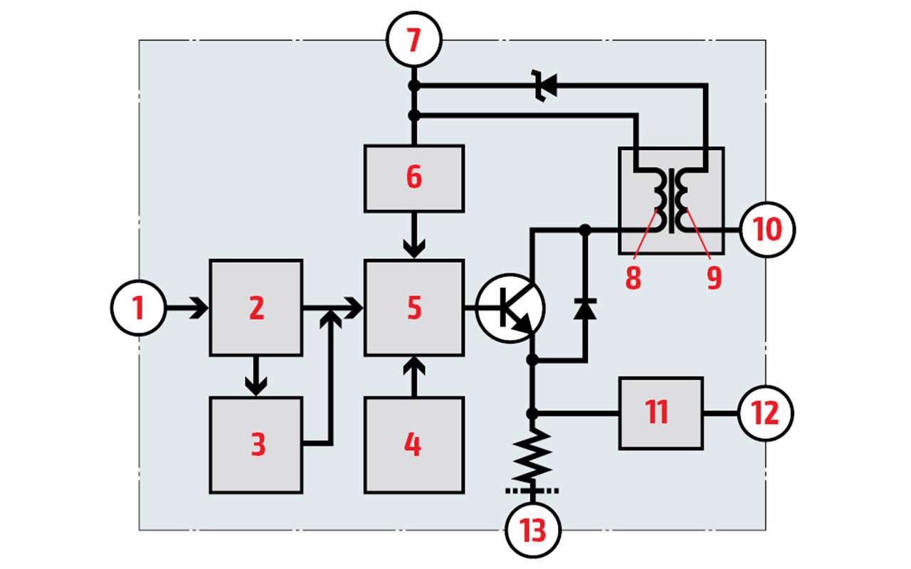
A regular coil only needs two wires – a constant plus and a controlled minus. In the more advanced four terminal coil, the electronic switching unit is mounted on top of the coil and the transformer is wound on a long core that runs along the coil. The block constantly needs plus and minus. Of the other two conclusions, one gives control – it gives the signal “it is time to spark”, and the second – feedback: whether sparks have occurred.
Obviously, most car owners looking under the hood may not even be aware of the presence of candles, coils, and other “incendiary” attributes. And they are. And will be for a long time. Talking about some kind of laser plasma candles that set fire to the mixture with a powerful beam, just keep talking until now.
- “Behind the wheel” can be read in Odnoklassniki.
Where do kilovolts come from under the hood, which ignites the working mixture in the cylinders, when the battery voltage barely exceeds 12 V? How many cables do the ignition coils have? You need to know this (and of course not only this) to avoid expensive repairs.